Operation Guide
Direction of Shaft Rotation
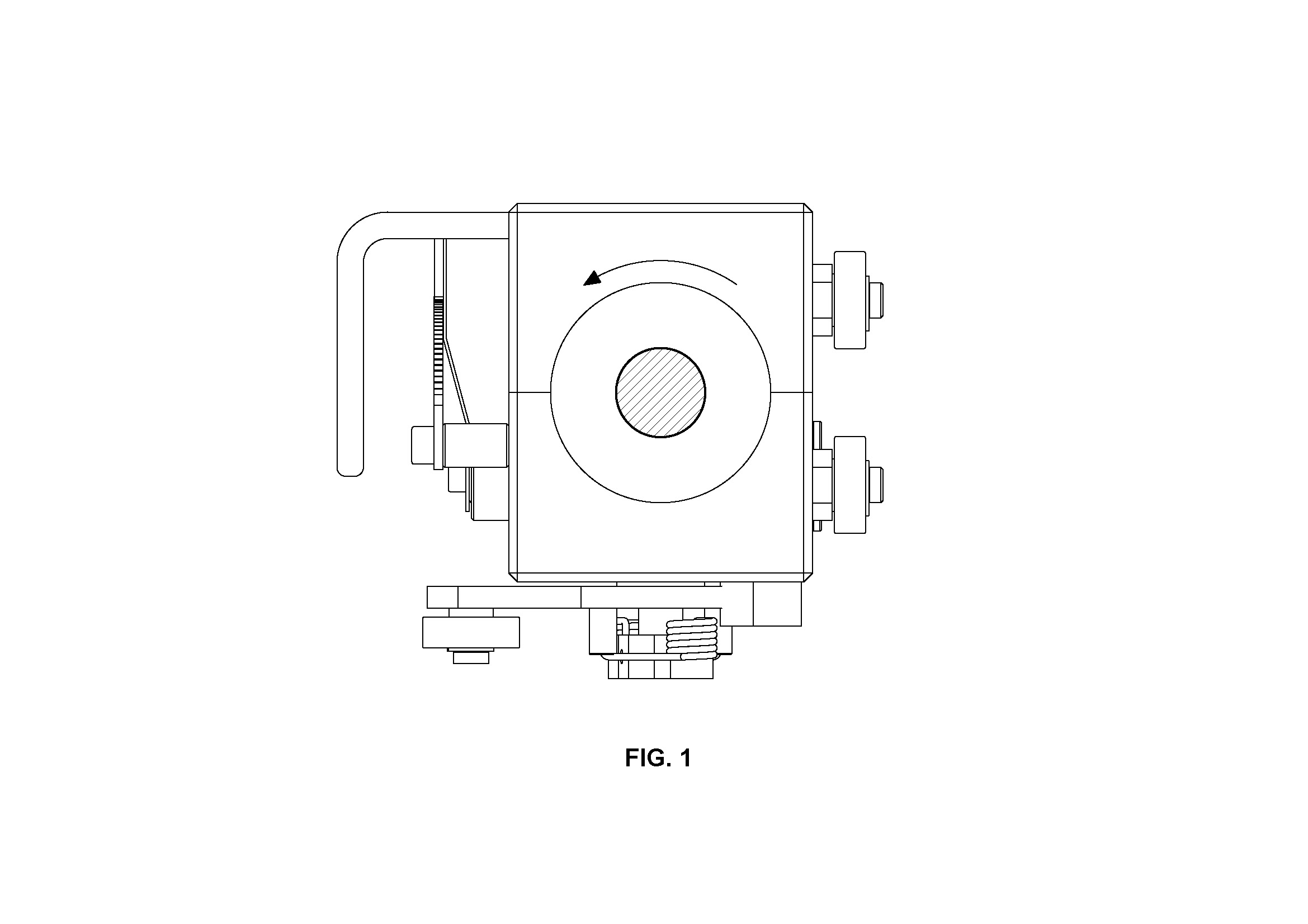
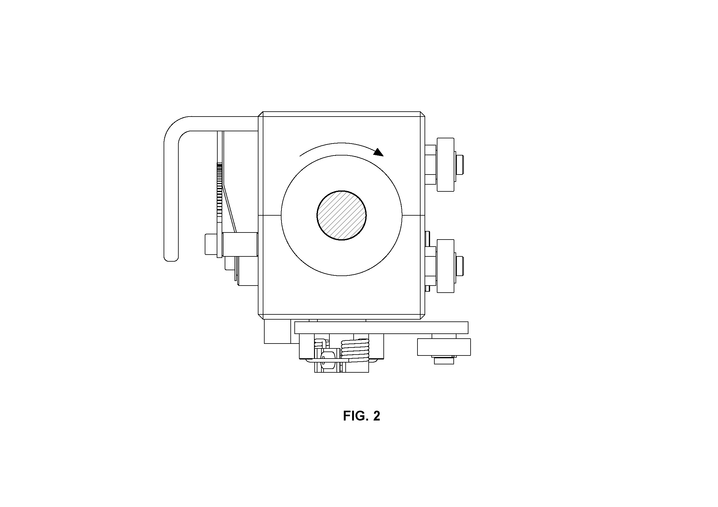
By default, Traverse units are typically configured for clockwise rotation of the shaft, unless specific requirements dictate otherwise. Here are two common orientations with explanations and visual references.
Clockwise Rotation
In this configuration, the Traverse unit is set up with the bearing on the reversal lever pointing towards the speed setting dial position. This aligns with the default clockwise rotation of the shaft.

Anti-Clockwise Rotation
For anti-clockwise rotation of the shaft, the Traverse unit is configured differently. In this case, the bearing on the reversal lever is positioned away from the speed setting dial, accomodating the anti-clockwise rotation of the shaft.


SIDE THRUST
This represents the maximum force that can be safely applied. If the force exceeds this value, the unit may slip.
PITCH
Pitch is the linear movement of the traverse unit for one rotation of the shaft. It is adjustable using the dial.
ADJUSTING THE PITCH
To adjust the pitch, press the pointer lever down and shift it along the dial for pitch variation.
LINEAR SPEED
The linear speed depends on the shaft speed and pitch setting.
SHAFT SPEED
Shaft speed is calculated in relation to the maximum pitch of the traverse unit and the maximum linear speed required.
SPOOLING APPLICATION
In spooling applications, drive to the traverse shaft is provided from the bobbin drive shaft to ensure automatic synchronization of speed. Maintain the speed ratio between the bobbin drive and traverse shafts for precise pitch adjustments.
LAYER WINDING APPLICATION
The speed ratio is calculated based on the maximum width or diameter of the material.
Installing Traverse Unit On The Shaft
Note: Chamfer the shaft end to 2X 300 to prevent damage to the rolling rings during installation.